Open topic with navigation

The Layout Assistant Dialog
|
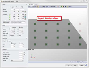
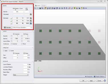
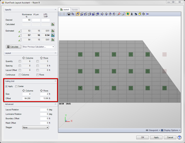
Operation of the ElumTools Layout Assistant utilizes two dialogs: the Selection dialog (not shown) and the Layout Assistant dialog (shown at right). When the Layout Assistant is selected, the first dialog that will appear is the Selection dialog. Operation of the Selection dialog is covered in both the Layout Assistant - Basic Operation and Layout Assistant Selection Dialog topics.
Once the inputs required by the Selection dialog are complete, control is transferred to the Layout Assistant dialog discussed in this topic. This is where the actual estimating, calculating and layout control is performed. The final layout and calculated results are exported to the current Revit view when your work in the this dialog is complete.
A description of the various functions of the Layout Assistant dialog are covered below.
|
 |
When the Layout Assistant dialog opens, the software is already prepared with an accurate description of the area you are working on through the inputs in the Selection dialog. Data such as Room or Space (or other bounding geometry), luminaire type, luminaire hosting, ceiling grid size and alignment are recorded. Some of these inputs can be adjusted if necessary, as you will see below.
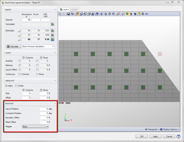
Specify section
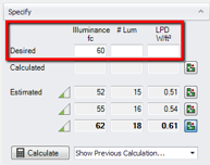
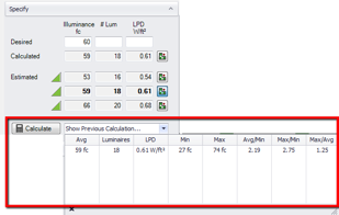
The Specify section is where you will start each layout by entering one of three possible estimating criteria: your desired light level, the luminaire quantity or target power density.
Desired
You will enter either a desired light level (average), a quantity of luminaires or a target value for power density to begin. Layout Assistant will produce three estimated layouts based on this input (see Estimated below). The preferred layout as judged by ElumTools is shown with bold type as the current layout. You can freely move from one estimated layout to another.
|
|
Calculated
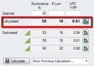
Results are not displayed on the Calculated line until a layout estimate has been calculated using the "Calculate" button. Once a layout has been calculated, the Layout Assistant will show the calculated average illuminance, luminaire quantity (# Lum) and lighting power density (LPD) for that layout in the "Calculated" line.
To calculate a layout, first select the layout by clicking on the icon at the right end of the line, then click the Calculate button.
|
|
Estimated
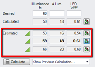
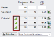
The Estimated area consists of three lines, each with a slightly different estimated layout based on the input received in the Desired section. The layout currently shown in the viewer will be shown in bold type and the icon at the right end of the line will be highlighted.
Once any of the estimated layouts is calculated using the Calculate button, the list of estimates is updated and accuracy improved.
|
|
Calculate button and Previous Calculation menu
To calculate a layout, select it from the list of estimates by clicking on the button at the right side of the estimate line, then click the Calculate button. Selected layouts appear in bold text with a highlighted button. The Layout Assistant will compute the results as if the luminaires had already been placed in Revit and you had selected the Calculate command*. The completed results are shown in the Layout Assistant viewer, which is similar to the standard ElumTools viewer.
Once a layout has been calculated its results will be shown in the Calculated line (discussed above). If more than one layout has been calculated, each calculation will be listed in the pull down menu for reference. Any previously calculated layout can be made the current layout by selecting it from the list.
* The Layout Assistant is unable to cut holes in geometry for recessed lights so you may observe very small differences when computing the room/space in Layout Assistant versus using the ElumTools Calculate Room/Space commands.
|
|
Confidence level - the green triangle
When you first begin using the Layout Assistant, each estimated layout will begin with a low-to-moderate confidence level, with the triangle only partially filled in green. This reflects ElumTools' best estimate, given the limited amount of known information. ElumTools' estimating technique is quite good, using a coarse radiosity solution for a single luminaire as its basis. Once any of the estimated layouts is calculated by using the Calculate button, the list of estimates is updated and the confidence level is improved. The more calculations ElumTools performs, the higher the confidence level in estimated results. Calculated layouts with a completely filled green triangle have a confidence level of 100%.
|
|
Layout section
The Layout section will display luminaire layout details for the currently selected estimate in terms of columns and rows. You can adjust the layout using any of the displayed data elements.

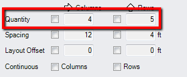
Quantity
Quantity describes the layout in terms of the number of columns and rows of luminaires. Either result can be adjusted by selecting the checkbox and entering the desired number in the cell. Keep in mind that when adjusting the number of rows or columns you are also adjusting the total quantity of luminaires and your light level will increase or decrease accordingly.
|
|
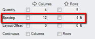
Spacing
Spacing displays the on-center spacing between luminaire columns and rows. If you have selected a ceiling grid, the results will be a whole number as a multiple of the ceiling tile size. Either or both columns can be adjusted by selecting the checkbox and entering the desired number in the cell. For example, if no ceiling grid is specified, you may see decimal results. Use the checkbox and enter a whole number if preferred.
Note: The resulting spacing will be equal to a whole-number multiple of the entered value. If the desired spacing is to be exactly the entered value, the Continuous box should also be selected.
|
|
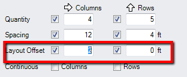
Layout Offset
You may often find it desirable to move the entire luminaire layout by some distance left-to-right or top-to-bottom. This is especially true when working in ceiling grid systems. To do this, enter a checkmark in either of the Layout Offset boxes (they behave the same way). When Offset is employed, the Quantity and Spacing boxes will also be checked. This freezes the layout in terms of quantity, columns, rows and spacing. You are then free to enter your desired Offset in either or both of the input cells provided.
|
|
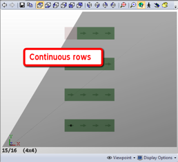
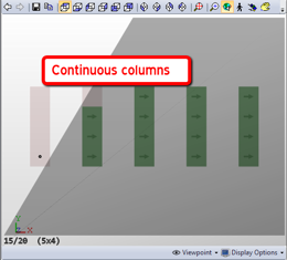
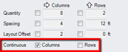
Continuous
The Continuous setting is provided for linear rows or columns where the luminaire spacing places the instances adjacent to one another. Either columns or rows can be set to be continuous. Enabling the setting for columns will reduce the luminaire spacing between rows. Enabling for rows will reduce the spacing between columns. Luminaires that are constrained by a ceiling grid may still be separated by adjacent ceiling tiles.
|
|
Ceiling Grid section
The Ceiling Grid section is hidden from view in default operation of the Layout Assistant. It can be opened by clicking the small arrow at the right side of the retractable heading bar. The selection of a ceiling grid size can be done in the Selection dialog by clicking three points. Those dimensions are then reflected in this section of the Layout Assistant dialog. Adjustments can be made using the various inputs provided, and the grid can be disabled all-together if necessary.
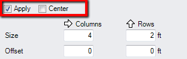
Apply and Center checkboxes
If you selected a ceiling grid size from the Selection dialog, the Apply checkbox is automatically enabled. You can remove the grid from consideration by unchecking the Apply setting. The ceiling grid can be centered in the Room (Space) by selecting the Center option. This may cause the grid to not be aligned with its position in Revit.
|
|
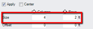
Grid Size
The grid size is calculated from the ceiling grid points set in the Selection dialog. If by chance you made an error, it can be corrected here. The grid size can also be changed but it may then not align with the Revit grid.
If you are working with a room that does not currently have a ceiling grid placed in Revit, you can experiment with adding one here. Simply click the Apply checkbox and enter a size. You can shift the grid by entering an offset (below).
|
|
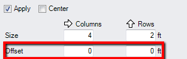
Grid Offset
To shift the ceiling grid horizontally, enter a value in the Columns cell. To shift the grid vertically, enter a value in the Rows cell. This number should be something less than the ceiling grid dimension. If you enter a value larger than the tile dimension it will be reduced when you exit the cell.
|
|
Advanced section
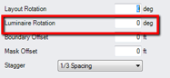
The Advanced section is normally hidden from view when the Layout Assistant opens. You can open it by clicking the small arrow at the right side of the retractable heading bar. The Advanced section allows for specification of layout rotation, luminaire rotation, boundary offset, mask offset, and staggered arrangement. These are not typical applications but may be required periodically.
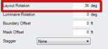
Layout Rotation
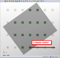
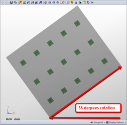
If you set a rotation angle or a ceiling grid that is not aligned with zero in the Selection dialog, the angle from zero (east, world coordinate zero) will be shown in the Layout Rotation cell in the Advanced section. This parameter can be adjusted so that your rows and columns are not in alignment with the room walls if desired. See the examples below.
|
|
|
|
Luminaire Rotation
Luminaires can be rotated while maintaining their place in the layout. This will be advantageous if the luminaire instance you have placed in the Room/Space was not set correctly, or in the event of an asymmetric light distribution. The rotation angle is always referenced with respect to due East (world coordinate zero) and measured counterclockwise.
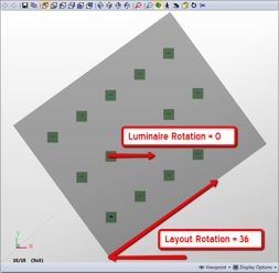
Luminaire Rotation is not automatically tied to Layout Rotation (above). For example, in the screen-shots above, the zero-degree Layout Rotation also shows a zero-degree Luminaire Rotation. The 36-degree Layout Rotation shows a 36-degree Luminaire Rotation. But in the example below, the 36-degree Layout Rotation shows a zero-degree Luminaire Rotation.
|
|
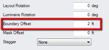
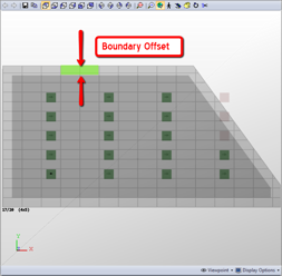
Boundary Offset
The Boundary Offset parameter is used to create a luminaire-free zone measured from the walls of the Room or Space. For example, a Boundary Offset of two feet will prevent any luminaires from being located closer than two feet from the walls (see below). The Boundary Offset is shown as a light gray border around the Room or Space.
Boundary Offset will also apply to any room bounding geometry that may be inside the Room or Space, such as columns.
|
|
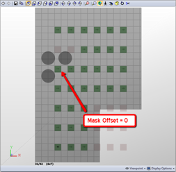
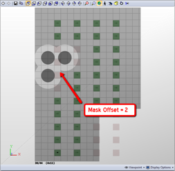
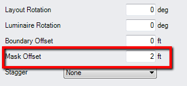
Mask Offset
Mask Offset is used to create a luminaire-free zone around any entities or areas you may have masked from the Selection dialog. The offset is shown as a light gray border around the entity or drawn area. See the example below.
|
|
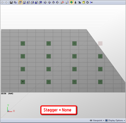
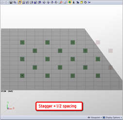
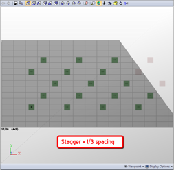
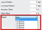
Stagger
The Stagger parameter allows columns to be staggered such that luminaire arrangement can be in a checkerboard pattern or similar, with the stagger distance set as a fraction of column spacing. For example, a 1/2 Spacing staggered arrangement shifts the luminaires to the right a distance equal to 1/2 the column spacing. Similarly, a 1/3 spacing staggered arrangement shifts the luminaires to the right a distance equal to 1/3 the column spacing. See below.
Be aware that the use of Staggered arrangements may place luminaires on grid lines for ceiling grids.
|
|
ElumTools copyright 2018 Lighting Analysts, Inc.